Do you know, even today in electrical energy landscapes, power thermal plants hold a remarkably significant advantage in the electricity generation paradox. Like never before, modern societal thoughts have shifted from conventional ways to carbon-intensive technologies and the integration of renewables.
Baked with IoT, and cloud computing technologies, the thermal plants have resulted in the digitalization of power plant performance addressing various needs of complex process outcomes and power utilities. Moreover; with ongoing advancements and the underlying trends, there are various important electrical appliances and devices classified based on switchgear augment found in almost every thermal-electrical power system and substations. Here, in this written document, let me surprise you with an in-depth understanding of the mechanism of the two most resilient power grid electrical instruments/devices- Isolator and Circuit Breaker along with their major Difference between Isolator and Circuit Breaker individually. Moreover, along with some comprehensive similarities between the two, one of the highlighted differences is that their electric symbols are different contributing unique roles in an electrical framework.
With efforts to increase safety and sustainable power, switchgear found in power generation plants plays a very vital role in controlling and protecting electrical power systems. In large electrical systems, under the umbrella of switchgear, Isolators, and Circuit Breakers’ functions and essentials are critically important for power distribution needs within the system. Therefore, both switchgear are the necessary components with some unique properties and differences.
Hence, the following description highlights the salient features and characteristics of the Isolator and Circuit Breaker in the below paragraph.
Table of Contents
Let’s begin with-
- Understanding of electrical Isolators
- Understanding About Isolators
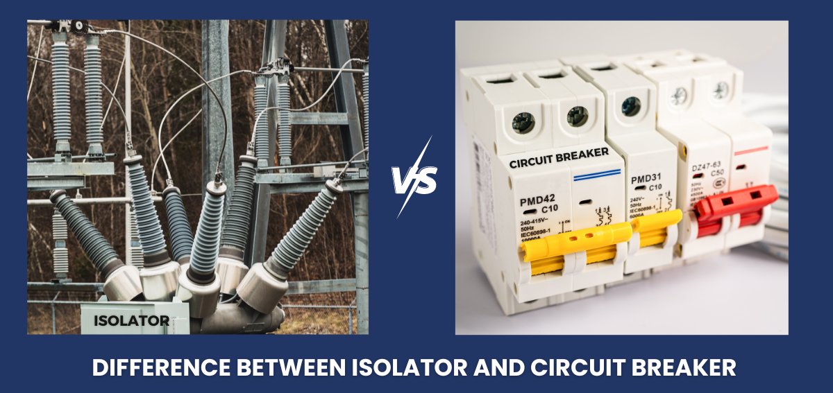
- Difference between Isolator and Circuit Breaker
- India’s Best Power Solution Manufacturers.
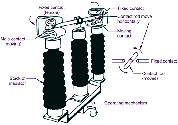
Essential Qualities of an Isolator– As the name suggests an isolator switch disrupts the electric circuit from the main power supply device and disconnects the electrical component under abnormal electrical conditions. The primary function is to protect the electrical appliances from serious accidental damage and ensure the utmost safety of the working professionals. In simple terms, an electrical isolator is a kind of mechanical switch that is designed to separate faulty electrical components/substations/ appliances from the power transformer depending on the necessities against the electrical shocks. It is also called a disconnecting switch that works on the Malus law of polarised light that works in the “ Off” position creating a break.
Generally, there are three types of electrical- isolator switches Double Break Type Isolator, Single Break Type Isolator, and Pantagraph Type Isolator based on the specification.
Rated Voltage-
- MV: 2kV- 36kV
- HV:5 kV- 800kV
Rated Current-
- MV: 400A- 1,250 A
- HV: 2,000 A- 5000 A
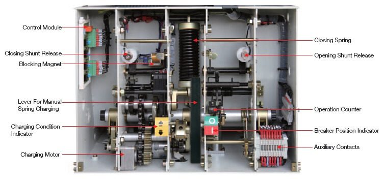
Essential Qualities of a Circuit Breaker– These are automatic electrical circuit switches or switch-on devices specially designed for certain conditions when there seems to be an electric fault. The primary function of this important switchgear comes under play when dealing with heavy load currents. This is a built-in extinguishing safety device that can be operated manually and automatically controlling the flow of heavy currents through a switch preventing short-circuit failures. In simple terms, circuit breakers are essential electric switchgear devices that interrupt an excess-current flow and resume normal operations. Circuit Breaker electrical switching devices are one of the most extremely trustworthy instruments when it comes to high temperatures and voltages.
In commercial or industrial testament areas, the electric current usually flows from the top – hot wire connecting the ground level forming another end. These are usually heavy closed power distribution grid units offering potential resistance to the flow of electric current charge to avoid any mishappenings in the form of industrial accidents.
Rated Current-
- Above 10k A
Mark the Main Difference between Isolator and Circuit Breaker
In the world of electrical systems, Isolators and Circuit Breakers hold eccentric functionality despite an ongoing debate on disparities and key Difference between Isolator and Circuit Breaker. Having said this, both these sets of electrical devices play an important role in running smooth operations. The purpose of an electrical isolator is to detach the current flow in an offloaded situation/ condition whenever there is a fault taking place from the main supply. They are performing the same purpose with different working and functioning mechanisms. On the contrary, the Isolator and disconnector electrical device do not need an Arc Suppression mechanism whereas Circuit Breakers work on it. When it comes to wiring, installation, and electric current and voltage, an arc suppression system is an optical sensor that measures the system load current during critical over-heating problems. This is also called an optical detection technology resulting in current-based conventional approaches. However; in essence, to facilitate the dealing of heavy electric current these units’ switchgear devices are widely used in various scenarios under the arch- the extinguishing ability to ensure safe maintenance after breaking the fault currents. Both isolator and circuit breaker electrical equipment serve as a perfect Confederate safeguarding device for ensuring maximum safety purposes against circuit overload.
Thus, having similar approaches they have distinct roles. Please follow the below paragraph to understand the comprehensive differences between the two best electrical components/ instruments in power supply thermal system plants.
Electrical Isolator | Circuit Breaker |
Definition- A protective electrical switch to disconnect the electric current to isolate the circuit to perform the preservation. | This is an electric switch to irrupt the electric flow of current |
Location– The electrical isolator is located at the main switchboard. | Circuit breakers are located somewhere in the low-traffic area of the operating premises/ space. |
Types– There are three types of isolator equipment- Double Break Type Isolator, Single Break Type Isolator, and Pantograph Type Isolator. | They are categorized as High Voltage Circuit Breakers and Low Voltage Circuit Breakers such as Air Circuit Breakers- ACB and MCCB- Molded Case Circuit Breakers. |
Mechanism- It opens the circuit part through a mechanical switch manually through a single point and breaks the current. | The circuit gets opened through an electromagnetic switch in the event of a circuit overload situation. |
Functioning- They are manual devices that work on offloaded conditions. | They are an automatic device that works on on-loading conditions. |
Withstand Capacity– They have low withstand thermal capacity. | They have a high withstand thermal capacity. |
So, both sets of components have certain similarities and differences between the two electrical components with different purposes in an electrical system. Also, we have discussed their distinctive attributes ensuring the loaded current does not regulate in damaging the electrical installation. Indeed, the post below will take you to one of the best-reputed circuit breakers and insulator manufacturers offering unbeatable real-world conditions for electrical instrumental devices all over the world.
Why Laxmi Associates Manufactures are Considered the Best Power System Solution
The notable Difference between Isolator and Circuit Breaker according to their withstand capability comparisons and unique characteristic properties is explained just above this paragraph. The above analysis aims to give you the best clarity subsequently to make the right selection that fits the best in your system use. Moreover; the mass production of industrial factories has gradually contributed to the key element of economic development over 20 years and to your surprise India’s power plant stations have become one of the largest sources of steam and burning fossil fuels like coal and gas in Asia- the largest continent. Moreover; when it comes to the electrical equipment manufacturing industry, Laxmi Associates in Vadodara( Gujarat) has left no stone unturned in emerging as the biggest global player in the Thermal Power Plant in India.
Furthermore, the multinational leading manufacturers have amalgamated into different sectors of industry disciplines and have become the topmost reliable and trustworthy choice in a diverse range of electrical appliance end-to-end power testing solutions across Asia and Africa. Also, household brand manufacturing is led by Dr. Aradhana Ray who is a Ph. D holder in electrical sciences with 24 years of experience making inevitable progress to mutified innovation.
In this way, you can play a strong decisive role in fulfilling the indispensable and substantial needs facilitating the integration of thermal power generation in an overall power distribution system.
The Final Words
The scale of electrical power is leading to revolutionary changes with the success of transition in various fields creating a huge impact on industrial sectors.
Isolators and Circuit breakers can be a significant investment in achieving a wide range of performing safe electrical operations. Moreover, these two devices have their plus and minus points and we have already drawn the line to discuss the difference between Isolator and Circuit Breaker, respectively. As the written article highlighted the difference between the two electrical device components; hence, it becomes easy for the user to select and choose between these switchgear appliances/instruments according to their specification and purpose. You can reach out to India’s best and foremost leading electrical appliance manufacturers based out in Vadodara at- https://laxmiassociates.in/
We hope the above article has provided valuable insights highlighting the salient information related to each topic.